Interpreting experimental TEM images is not always a trivial task and can sometimes be misleading. TEM image simulation is a useful tool to help interpret and clarify things that are seen in experimental images. There are several different image simulation programs available. The main program that the Crozier group uses is called JEMS which was developed and maintained by Dr. Pierre Stadelmann.
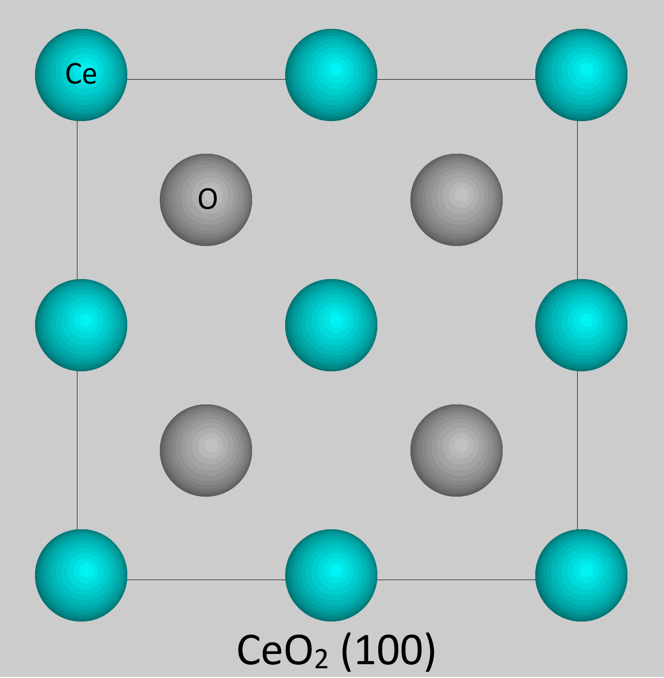
Image simulation requires some knowledge about the crystal structure and microscope parameters. For example, shown below is a CeO2 (100) unit cell.
There are many different parameters that play a role in forming an image in a TEM. Several of these include sample thickness, defocus, accelerating voltage, and aberrations. Small changes in these parameters can induce large changes in the image so it is very important to know and/or tune these values to a desired level. For example, shown below is a map of simulated images of 2×2 unit cells of CeO2 (100). Each column corresponds to a different defocus value while each row is a different thickness. An overlay of the CeO2 atomic positions is also shown for convenience in the top-right image.
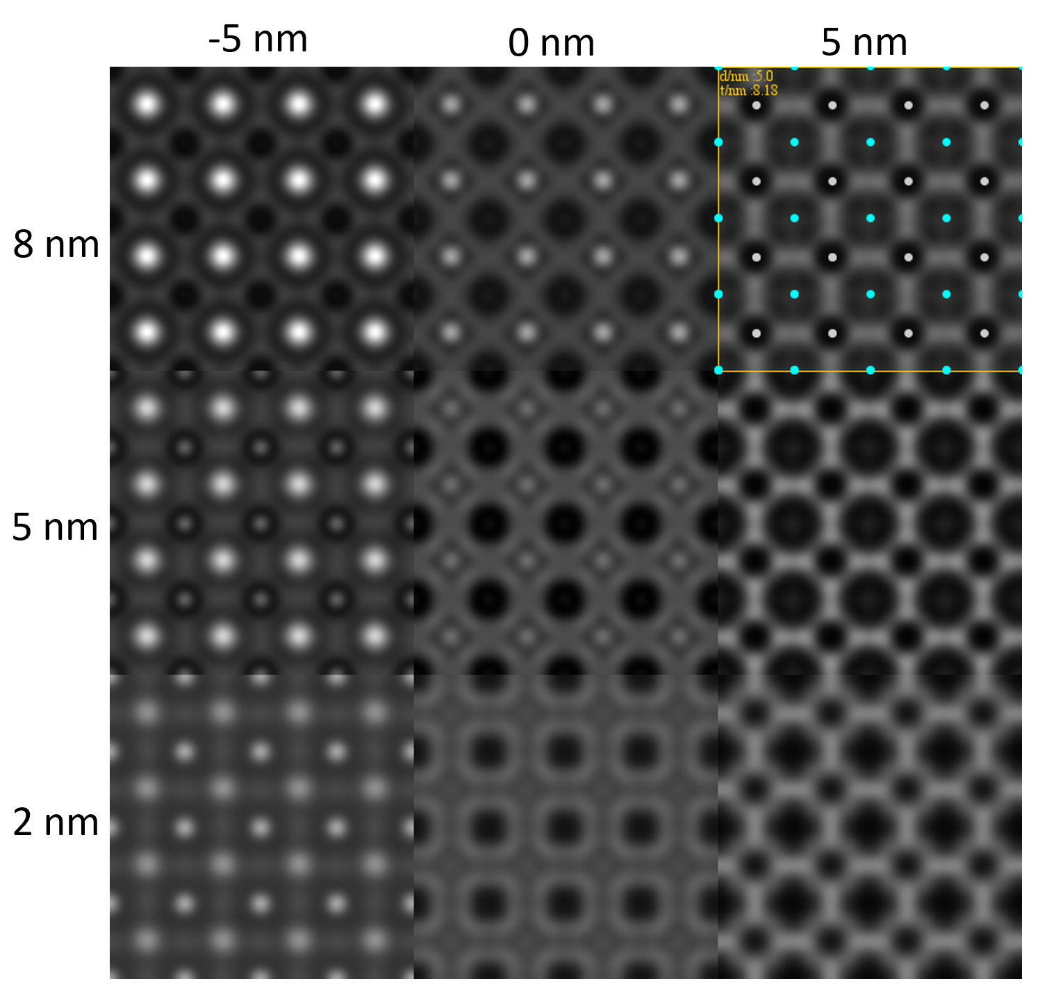
These images can be used to compare to experimental images or to determine favorable conditions for imaging before looking at the actual sample. Image simulation is an essential tool to accurately assess structural information seen in experimental TEM images.